FAYYAZ ELECTRIC / TECHNICAL KNOWLEDGE CENTER / PLC ENGINEERING
SIEMENS AUTOMATION • CONTROLLER ENGINEERING • 2026 FIELD GUIDE
Siemens SIMATIC S7-1200 PLC: A Practical Engineering Guide
Hardware selection, wiring fundamentals, I/O scaling, TIA Portal workflow, PROFINET / Modbus communication and a systematic commissioning checklist — with an important distinction between the classic S7-1200 and the newer S7-1200 G2.
ENGINEERING GUIDE12 MIN READOCT 2026REFERENCE-BASED
Actual Siemens SIMATIC S7-1200 hardware with I/O modules. Photograph: UlrichAAB / Wikimedia Commons (CC BY-SA 3.0); no changes made to the source file. This early-generation photograph is illustrative; the specifications below refer to identified CPU order numbers.
01 / PLATFORM OVERVIEW
Where the S7-1200 fits in industrial automation
The SIMATIC S7-1200 is Siemens’ compact modular programmable logic controller (PLC) family for machine and plant automation. It combines CPU processing, integrated inputs and outputs, an industrial Ethernet interface, and expansion options in one cabinet-friendly platform. Typical applications include pump stations, ventilation systems, small production machines, conveyor systems, automatic transfer auxiliaries, instrumentation acquisition and remote HMI control.
Do not treat S7-1200 as a single fixed hardware specification. CPU 1211C, 1212C, 1214C, 1215C and 1217C differ in integrated I/O, memory, network interfaces and expansion capacity. The electrical characteristics also change with the suffix AC/DC/Relay, DC/DC/Relay or DC/DC/DC. Always use the complete Siemens order number rather than the abbreviated CPU family name for procurement, wiring and software compatibility. [1]
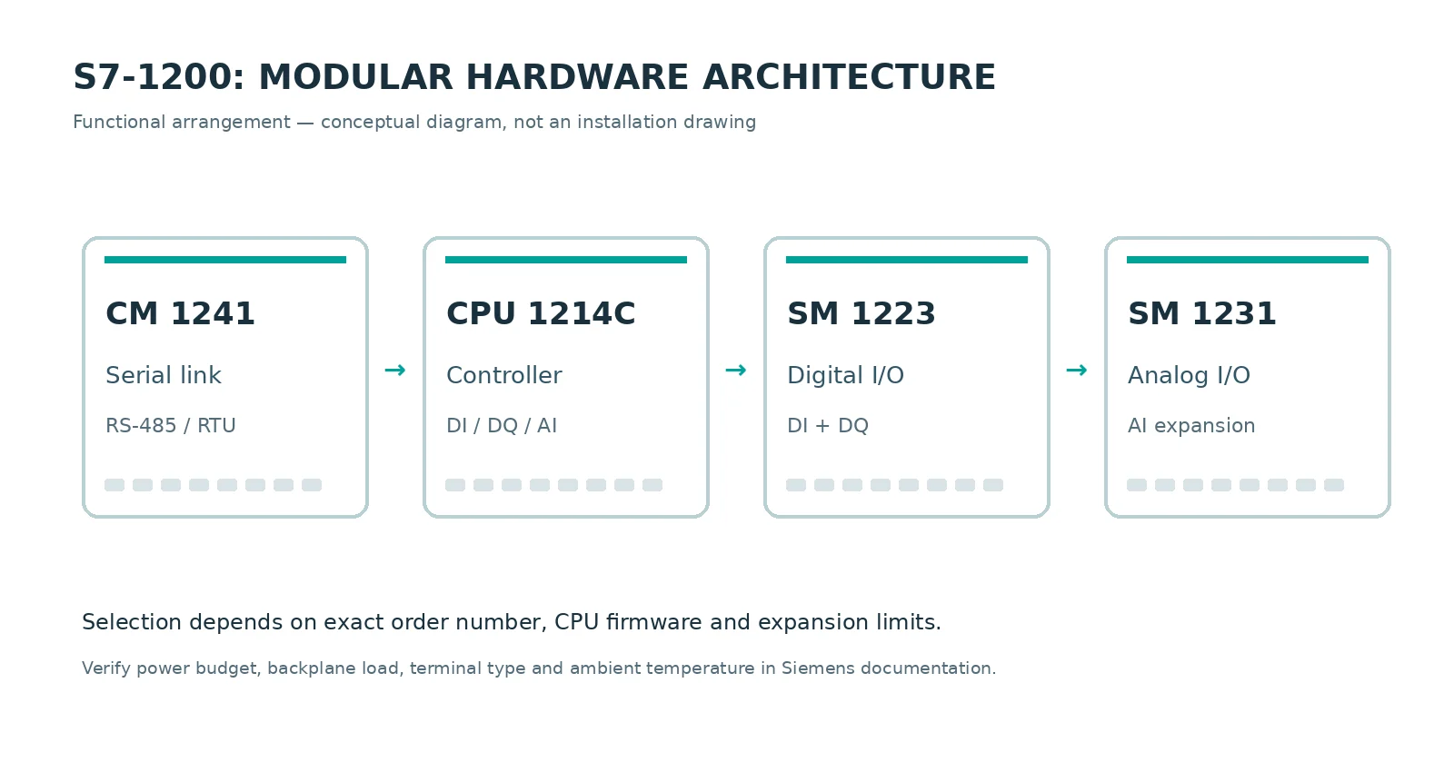
Original FAYYAZ Electric functional diagram: communication modules normally mount on the CPU’s left and signal modules on its right. Verify the actual permitted expansion configuration.
ENGINEERING RULE
Design from the I/O list and communications matrix first, then choose the CPU and expansion modules. Selecting only by the number of digital points is a frequent source of redesign during commissioning.
02 / CPU SELECTION
A real configuration example: CPU 1214C DC/DC/DC
The Siemens 6ES7214-1AG40-0XB0 is an identifiable classic S7-1200 CPU 1214C variant. Siemens’ current product listing and datasheet describe 14 × 24 V DC digital inputs, 10 × 24 V DC transistor digital outputs and 2 × 0–10 V analog inputs. Its nominal 24 V DC supply is specified as 20.4–28.8 V DC, with 150 KB work memory in the referenced revision. These data apply to that order number, not to every CPU 1214C. [2]
ONBOARD INPUTS14 DI24 V DC
ONBOARD OUTPUTS10 DQDC transistor
ONBOARD ANALOG2 AI0–10 V DC
WORK MEMORY150 KBSpecified revision
Real Siemens CPU 1214C in an earlier S7-1200 system. Photographer: UlrichAAB / Wikimedia Commons, CC BY-SA 3.0.
Before ordering
Check the power-supply version and digital-output technology. Relay outputs and DC transistor outputs are not electrically interchangeable. Verify output-current ratings, inductive load suppression, the power budget for expansion modules, and whether analog current signals require an additional signal module.
Confirm the required TIA Portal release against the chosen CPU firmware and product entry. A part number alone does not establish software compatibility for an existing project.
Quick selection matrix — classic family
CPU
Integrated DI
Integrated DQ
Integrated AI
Signal modules (max.)
1211C
6
4
2
0
1212C
8
6
2
2
1214C
14
10
2
8
1215C
14
10
2 AI + 2 AO
8
1217C
14
10
2 AI + 2 AO
8
Classic-family comparison from the Siemens S7-1200 system manual. These are core I/O categories; speed, HSC/PTO capability, work memory, PROFINET ports and current limits must be checked separately for the exact CPU and firmware. [3]
03 / REAL COMPONENT PHOTOGRAPHY
See the actual hardware before specifying modules
These are genuine photographs of commercially available Siemens components, not AI-generated equipment mockups. The pictured modules are examples of the classic S7-1200 family; ordering codes and supported signal types must still be confirmed individually.
Installed S7-1200 CPU 1212C with CSM 1277 and SM 1234. Photo source: NDLA.SM 1223 digital I/O module, real product photograph. Photo source: RS.SM 1231 analog-input module, real product photograph. Photo source: 4IND.
Media credits and ownership remain with the named photographers, manufacturers and publishers. See the image-use notes at the end of this article.
04 / TIA PORTAL WORKFLOW
Configuring and programming S7-1200 in TIA Portal
Siemens STEP 7 in TIA Portal is used to create the project, select hardware and firmware, assign PROFINET parameters, configure I/O, write PLC logic, download and run online diagnostics. For classic S7-1200, common IEC 61131-3 programming approaches include LAD, FBD and SCL; exact features depend on engineering software and CPU firmware.
Authentic TIA Portal device-selection screenshot from Control.com. The screenshot illustrates an older TIA version; menus and CPU data vary in current releases. Source.
Define device and firmware. Create a PLC device with the correct Siemens article number and firmware revision; add all actual signal and communication modules.
Set network parameters. Assign the CPU name and IP address in accordance with the plant IP plan; avoid duplicate addresses and unauthorized routing.
Map signals. Build a documented I/O list and PLC tags for sensors, permissives, alarms, contactors and HMI feedback.
Structure program blocks. Separate process sequencing, interlocks, alarms, communications and diagnostics into reusable FCs/FBs and instance DBs.
Compile, download and test. Confirm project and online device match, validate outputs with the machine in a safe test condition, then document as-built changes and backups.
REAL VIDEO — SIEMENS-DOCUMENTED FIRST STEPS
Siemens’ own TIA Portal documentation links to an introductory S7-1200 video that demonstrates project creation, hardware detection and device download. Watch it in the video section below. [4]
05 / CABINET DESIGN
Wiring, power and safety practices
Design the control panel around the actual CPU supply and output technology. A DC/DC/DC model typically uses a regulated 24 V DC supply, 24 V DC digital inputs and transistor outputs; an AC/DC/Relay variant may be powered from mains and provides dry-contact relay outputs. The correct wiring diagram is the one printed for the exact order number.
Digital inputs
Verify sourcing/sinking arrangement, sensor common, input filter times and cable shielding. Keep field wiring identifiable and segregate sensitive signals from VFD output cables.
Transistor outputs
Observe output load/current limits and external DC load supply; use interposing relays or contactors where required. Add appropriate suppression for inductive loads.
Analog inputs
CPU integrated analog channels on the cited 1214C variant are voltage inputs. Use the specified signal module for 4–20 mA instrumentation and match shield/ground treatment to the installation manual.
Machine safety
Standard PLC application logic is not a substitute for a validated safety function. Emergency stops, protective doors and hazardous-motion prevention require an appropriate safety architecture, such as a certified safety relay or safety-rated F-CPU and wiring.
Siemens’ system manual includes device-specific guidance on grounding, cable routing, isolation, analog values and module installation. Apply relevant requirements of IEC 60204-1 for electrical equipment of machinery and a risk-assessed safety standard such as ISO 13849-1 or IEC 62061 where applicable. Do not energize commissioning outputs until a site-specific risk assessment is complete. [3]
06 / INDUSTRIAL COMMUNICATIONS
PROFINET, Ethernet, Modbus TCP and serial options
The classic S7-1200 provides a built-in Ethernet/PROFINET interface for engineering access, supported HMI connections and PROFINET communication, with specific capabilities and connection limits defined by the CPU. Modbus TCP can run over the CPU PROFINET connector using Siemens’ MB_CLIENT and MB_SERVER instructions — no separate serial module is required for Modbus TCP. [5]
Modbus RTU over RS-485 is different: a compatible serial communication module/board such as a CM 1241 is required along with the appropriate protocol instructions. Do not connect an RS-485 instrument directly to the CPU’s Ethernet port. Communication configuration must include addressing, baud rate, parity, device timeouts and behavior on link loss.
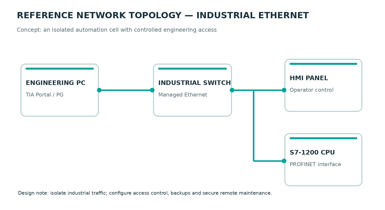
Original FAYYAZ Electric network concept. Not an as-built wiring diagram or a cybersecurity certification.
Interface / protocol
Typical use
Engineering note
PROFINET / Ethernet
HMI, distributed I/O and PG access
Exact I/O controller capability, device limits and CPU ports depend on model.
Modbus TCP
Power meters, drives and third-party Ethernet equipment
Use MB_CLIENT / MB_SERVER and confirm register maps, endian format and timeout behavior.
Modbus RTU
RS-485 meters, drives and serial transmitters
Requires suitable CM/CB; configure line termination and common reference.
OPC UA
Supervisory integration on supported classic CPUs
Check CPU firmware, license and Siemens’ documented security configuration.
07 / MEASUREMENT ENGINEERING
Analog scaling: never use raw counts as process units
For an applicable S7-1200 unipolar analog input configured for 0–10 V, the Siemens nominal data representation spans 0 to 27,648 counts. If a transmitter maps 0–10 V to 0–100% process output, the conceptual calculation is PV (%) = Raw × 100 / 27,648. This is a demonstration of nominal linear scaling, not a universal formula for every input range.
Original engineering plot: nominal 0–10 V to 0–100% transformation. The transmitter’s engineering range determines actual units.
EXAMPLE / PSEUDO-SCL — NOT A VERIFIED HARDWARE PROJECT
// Illustrative algorithm, not a drop-in TIA program.
// AI_Raw is already acquired from the configured channel.
IF (AI_Raw >= 0) AND (AI_Raw <= 27648) THEN
    PV_Percent := INT_TO_REAL(AI_Raw) * 100.0 / 27648.0;
    PV_Valid := TRUE;
ELSE
    PV_Valid := FALSE;
END_IF;
// Real projects also handle module diagnostics, wire-break,
// engineering-unit limits, filtering and failure defaults.
When the instrument is 4–20 mA rather than 0–10 V, choose the correct current-input module and configure the correct raw range. Do not reapply the 0–10 V formula to a 4–20 mA signal. Include under-range detection, noise filtering, sensor validation and a defined fallback state for loss of signal. See Siemens’ analog processing and hardware-module manuals. [6]
08 / SITE COMMISSIONING
Commissioning sequence that prevents repeat visits
01Verify power before plug-in. Measure supply voltage and polarity, fuse ratings, PE continuity and circuit separation with the panel safely isolated.
02Inspect I/O and expansion. Confirm each installed module and address against the approved drawings and the online hardware configuration.
03Check field signals individually. Test DI, DQ through safe simulated loads, analog ranges, instrument faults and sensor disconnects.
04Validate stop states. Confirm the required safe condition for CPU STOP, power loss, communication loss, E-stop and field-device fault.
05Test communications. Verify PROFINET device names, IP addressing, meter/drive mapping, watchdogs, timeouts and HMI indications.
06Archive the commissioned version. Store software, firmware revisions, I/O test sheets, parameter backups and approved as-built drawings.
Verify zero-/one-based register offsets, data type, byte/word order and error status.
09 / IMPORTANT 2026 UPDATE
Classic S7-1200 versus the newer S7-1200 G2
SIMATIC S7-1200 G2 is a distinct hardware generation, not simply a firmware upgrade of an existing classic CPU. The newer platform offers redesigned modules and cabinet footprint, improved performance, updated motion capabilities and different integrated I/O options. A project migration therefore requires a checked hardware/feature mapping and possible program changes; it is not safe to assume drop-in mechanical or functional compatibility.
The Siemens migration guideline (May 2026, revision 1.3) discusses differences in I/O, memory, communication, technology objects and web access. Some capabilities depend on G2 firmware version and product lifecycle. Check Siemens’ latest documentation at the time of design and do not transfer old feature tables directly to G2. [7]
PROCUREMENT ALERT
When replacing a failed classic CPU, verify availability and mechanical, electrical, I/O, network and software compatibility with the exact replacement article number. G2 support is not a reason to silently substitute modules without engineering validation.
10 / REAL VIDEO LIBRARY
Watch the actual hardware and TIA Portal workflow
These are genuine YouTube videos from identifiable publishers. The importer preview shows a clickable visual card; on the published WordPress page, the updated importer can also render the native YouTube player. Videos are hosted by their respective publishers and remain subject to their availability.
Getting started with SIMATIC S7-1200 and TIA Portal
Linked in Siemens’ TIA Portal first-steps documentation. Project creation, hardware detection, CPU settings and download. Siemens reference.
[fe_youtube id=”APV5qfgBunw”]
Siemens SIMATIC S7-1200 — Part 1: Getting Started
Original introduction from the SiemensIndustryUS channel. Historic interface shown; verify all settings against current software.
[fe_youtube id=”-Au6m45GIvA”]
Introduction to TIA Portal for S7-1200 PLCs
Independent educational walk-through published by Électricité-FP (2024), including basic configuration and simulation.
[fe_youtube id=”ciu7e1wJu8Y”]
11 / ENGINEERING CONCLUSION
Design for the actual machine, not just the controller’s label
The classic S7-1200 can be an effective choice for compact machine and process control when its electrical I/O, communications, memory, cycle time and safety interfaces have been assessed against the application. The most reliable projects start from a verified I/O list, complete CPU article numbers and documented operating states — then progress through structured TIA Portal programming and systematic commissioning.
For new projects in 2026, compare classic availability with the G2 roadmap using current Siemens data. For maintenance and retrofit projects, prioritize compatibility, known spare parts and proven site-specific validation.
FAYYAZ Electric provides industrial control-panel engineering, PLC/HMI integration, installation, commissioning and troubleshooting in Erbil and across Iraq. For technical consultation, contact FAYYAZ Electric .
Additional product/screenshot photo credits and original publisher links appear directly below each image. Siemens and SIMATIC are Siemens trademarks. This is an independent technical article, not an official Siemens manual or a claim of endorsement. Third-party product photographs may require reproduction permission; verify rights before enabling external-image import or publication.
Editorial review date: 29 October 2026. Specifications cited are model-/firmware-specific. Validate all part numbers, software support and safety requirements against the current manufacturer documentation and project specifications.
What if an air circuit breaker could evolve when the power-distribution strategy changes? MasterPacT MTZ turns that question into an engineering discussion about modular protection, electrical measurements and maintenance, not simply a replacement exercise. Practical selection guidance, wiring decisions and a test checklist.
A large circuit breaker can look ready long before a switchboard is ready. The Siemens 3WA illustrates why mounting, racking, protection and control wiring deserve independent checks—especially when the final commissioning window is short. Practical selection guidance, wiring decisions and a test checklist.
An ACB commissioning problem often looks mechanical until the engineer discovers a communications setting, a missing module or an untested alarm map. ABB Emax 2 and the Ekip ecosystem deserve a workflow that treats protection and connectivity as two independent commissioning disciplines. Practical selection guidance, wiring decisions and a test checklist.
A conventional starter says “running” and “tripped”. In a connected machine the engineer may need load information, diagnostics and repeatable motor control. TeSys island is Schneider Electric’s answer, built around digital motor-management concepts. Practical selection guidance, wiring decisions and a test checklist.
The critical ATS question is not “Will the generator start?” It is “What happens to the load while sources disappear, return, fluctuate and disagree?” ABB TruONE combines the automatic transfer controller and switch, but the source-transfer philosophy must still be engineered. Practical selection guidance, wiring decisions and a test checklist.
The fastest way to derail a PLC retrofit is to assume the new CPU accepts every existing expansion and project version. The S7-1200 G2 brings a redesigned platform, but software, I/O and hardware compatibility need a deliberate check. Practical selection guidance, wiring decisions and a test checklist.
Robot controllers are increasingly capable, but the integration failure usually happens between the robot and the rest of the machine. OmniCore is a timely reason to revisit handshakes, protective stops and how an HMI communicates the real robot state. Practical selection guidance, wiring decisions and a test checklist.
A smart power meter can report dozens of parameters and still tell the wrong story if one CT polarity is reversed. The PowerLogic PM8000 is best introduced through real commissioning mistakes, not marketing specifications. Practical selection guidance, wiring decisions and a test checklist.
The first MS300 start is often easy; the difficult part is guaranteeing the motor behaves correctly when a contact opens, a setpoint disappears or the operator switches to manual mode. Those are the settings that separate a demonstration from a reliable installation. Practical selection guidance, wiring decisions and a test checklist.
Does your drive only need to change motor speed—or must it help diagnose the next unplanned stop? Siemens positions the SINAMICS G220 for modern industry, and its value is best judged against a specific production problem. Practical selection guidance, wiring decisions and a test checklist.
Long sensor cable runs, crowded marshalling terminals and poor I/O diagnostics make small machine upgrades surprisingly expensive. Modular remote I/O offers a different architecture—but only when the PLC scanner, coupler and addressing are commissioned together. Practical selection guidance, wiring decisions and a test checklist.
A remote-I/O coupler that fits the DIN rail may still be incompatible with your PLC. ARIO is a useful case study in the difference between a modular physical platform and the protocol-specific device hiding inside it. Practical selection guidance, wiring decisions and a test checklist.